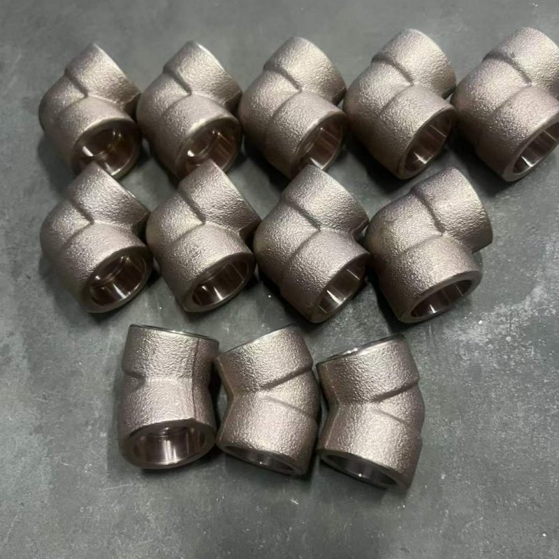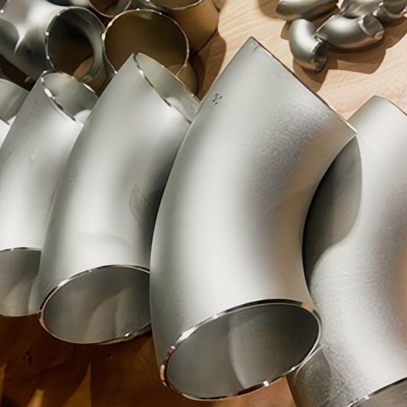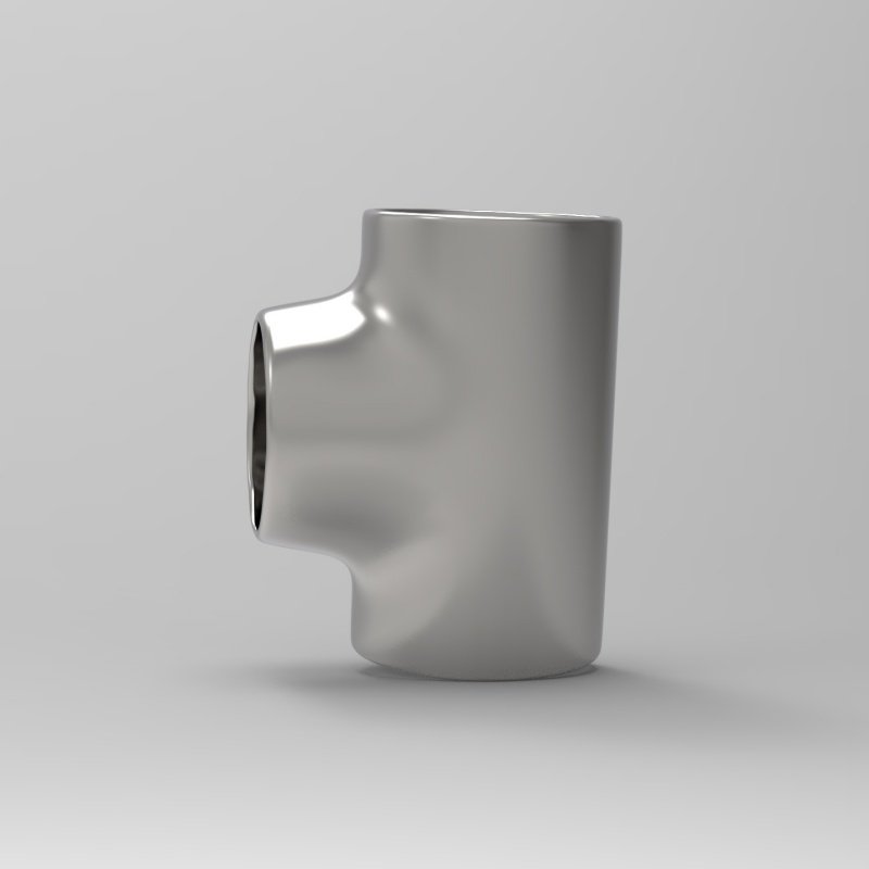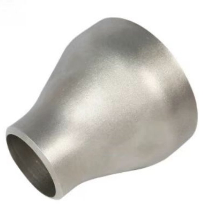


Duplex stainless steel fittings are supplied in four forging grades
under ASME SA-182 and two wrought grades under ASME SA-815, covering the 2205 and
super duplex 2507 families. This page is the grade-selection entry point: it maps the
UNS numbers, the forging and wrought designations, the heat treatment and the
inspection regime so that the correct grade is written on the order before the
dimensions are discussed.
For dimensional standards, pressure classes and flange mating, see our
nickel
alloy butt weld fittings and
forged
socket weld fittings ranges.
Grade Designations and UNS Mapping
| Trade description | Forging grade (SA-182) | Wrought grade (SA-815) | UNS | SA-182 Table 4 filler description |
|---|---|---|---|---|
| 2205 (older chemistry) | F 51 | WPS31803 / CRS31803 | S31803 | 22 % Cr, 5.5 % Ni, 3 % Mo |
| 2205 (current) | F 60 | WPS32205 / CRS32205 | S32205 | 22 % Cr, 5.5 % Ni, 3 % Mo |
| Super Duplex 2507 | F 53 | WPS32750 / CRS32750 | S32750 | 25 % Cr, 7 % Ni, 4 % Mo |
| Super Duplex, tungsten-bearing | F 55 | WPS32760 / CRS32760 | S32760 | 25 % Cr, 7 % Ni, 3.5 % Mo |
SA-182 Table 4 note F: NR = not required. SA-182 Table 4 note I: matching filler
metal is available. SA-815 Table 1 note A: the grade WP and CR naming system was
developed by ASTM International.
Chemical Composition (ASME SA-182, Table 2)
| Element, % | F 51 / S31803 | F 60 / S32205 | F 53 / S32750 | F 55 / S32760 |
|---|---|---|---|---|
| Carbon, max | 0.030 | 0.030 | 0.030 | 0.030 |
| Manganese, max | 2.00 | 2.00 | 1.20 | 1.00 |
| Phosphorus, max | 0.030 | 0.030 | 0.035 | 0.030 |
| Sulfur, max | 0.020 | 0.020 | 0.020 | 0.010 |
| Silicon, max | 1.00 | 1.00 | 0.80 | 1.00 |
| Nickel | 4.5 – 6.5 | 4.5 – 6.5 | 6.0 – 8.0 | 6.0 – 8.0 |
| Chromium | 21.0 – 23.0 | 22.0 – 23.0 | 24.0 – 26.0 | 24.0 – 26.0 |
| Molybdenum | 2.5 – 3.5 | 3.0 – 3.5 | 3.0 – 5.0 | 3.0 – 4.0 |
| Nitrogen | 0.08 – 0.20 | 0.14 – 0.20 | 0.24 – 0.32 | 0.20 – 0.30 |
| Copper, max | not required | not required | 0.50 | 0.50 – 1.00 |
| Tungsten, Other Elements | not required | not required | not required | 0.50 – 1.00 |
SA-182 Table 2 note A: values are maxima unless a range or minimum is indicated.
SA-815 Table 1 note C: for the tungsten-bearing grade, % Cr + 3.3 × % Mo + 16 × % N
= 40 min. SA-790 Table 2 note D for S32750 and note E for S32760 state the corresponding
pipe requirements as % Cr + 3.3 × % Mo + 16 × % N ≥ 41 and
% Cr + 3.3 × (% Mo + 0.5 × % W) + 16 × % N ≥ 41.
Mechanical Properties
| Grade | SA-182 Table 3: tensile, min, ksi [MPa] | Yield, min, ksi [MPa] | Elongation, min, % | SA-815 Table 3: yield, min, ksi [MPa] | Tensile, ksi [MPa] | Elongation, min, % | HBW, max |
|---|---|---|---|---|---|---|---|
| F 51 / S31803 | 90 [620] | 65 [450] | 25 | 65 [450] | 90 [620] | 20.0 | 290 |
| F 60 / S32205 | 95 [655] | 70 [485] | 25 | 65 [450] | 95 [655] | 20.0 | 290 |
| F 53 / S32750 | 116 [800] | 80 [550] | 15 | 80 [550] | 116 [800]–140 [965] | 15.0 | 310 |
| F 55 / S32760 | 109–130 [750–895] | 80 [550] | 25 | 80 [550] | 109 [750]–130 [895] | 25.0 | 270 |
SA-182 Table 3 note B: yield strength is determined by the 0.2 % offset method.
SA-815 Table 3 note A: minimum unless otherwise indicated. SA-790 Table 3 gives
S32760 a tensile minimum of 109 ksi [750 MPa] and carries note B recording that the
value was previously 109–130 ksi [750–895 MPa] prior to A790/A790M-04, which
is why the forged and pipe documents still show a range for that grade.
Heat Treatment
| Grade | SA-182 Table 1 | SA-815 Table 2 | SA-790 Table 1 (pipe) |
|---|---|---|---|
| F 51 / S31803 | 1870 °F [1020 °C] min, liquid quenched | 1870–2010 °F [1020–1100 °C], water quench | 1870–2010 °F [1020–1100 °C] |
| F 60 / S32205 | 1870 °F [1020 °C] min, liquid quenched | 1870–2010 °F [1020–1100 °C], water quench | 1870–2010 °F [1020–1100 °C] |
| F 53 / S32750 | 1880 °F [1025 °C] min, liquid quenched | 1920–2060 °F [1025–1125 °C], water quench | 1880–2060 °F [1025–1125 °C] |
| F 55 / S32760 | 2010–2085 °F [1100–1140 °C], liquid quenched | 2010–2085 °F [1100–1140 °C], water quench | 1960–2085 °F [1070–1140 °C] |
SA-182 7.3 requires the austenitic and ferritic-austenitic stainless steels to be heat
treated and liquid-quenched in accordance with 7.1 and Table 1, and SA-182 7.3.1 allows
ferritic-austenitic grades to be solution annealed without cooling below 1000 °F by
being re-heated to the solution annealing temperature required in Table 1, held for a
time sufficient to dissolve phases and precipitates which may cause a reduction in
corrosion or mechanical properties, and quenched in accordance with Table 1. SA-182
Table 1 note A: minimum unless temperature range is listed. SA-815 Table 2 records the
tempering temperature as not required for all ferritic/austenitic grades.
Size Range and Dimensional Standards
SA-815 10.1 requires the sizes, shapes and dimensions of the fittings covered by
ASME B16.9, ASME B16.11, MSS SP-43, MSS SP-79, MSS SP-83, MSS SP-95 or MSS SP-97 to
be as specified in those standards, and SA-815 10.2 permits fittings of a size or shape
differing from those standards, but meeting all other requirements of the
specification, to be furnished in accordance with Supplementary Requirement S58 of
A960/A960M. Fittings are ordered by nominal size and the governing dimensional
standard, not by outside diameter and wall thickness.
The pipe that a fitting must match is dimensioned to the ANSI B36.19 series given in
ASME SA-790 Appendix Table X1.1, from NPS 1/8 to NPS 30, with schedules 5S, 10S, 40S
and 80S. Schedule 5S and 10S wall thicknesses do not permit threading in accordance
with ANSI B1.20.1, and the wall thicknesses marked in Table X1.1 do not conform to
ANSI B36.10-1979.
| NPS | OD (in) | OD (mm) | Sch 5S (in / mm) | Sch 10S (in / mm) | Sch 40S (in / mm) | Sch 80S (in / mm) |
|---|---|---|---|---|---|---|
| 1/8 | 0.405 | 10.29 | — | 0.049B / 1.24 | 0.068 / 1.73 | 0.095 / 2.41 |
| 1/4 | 0.54 | 13.72 | — | 0.065B / 1.65 | 0.088 / 2.24 | 0.119 / 3.02 |
| 3/8 | 0.675 | 17.15 | — | 0.065B / 1.65 | 0.091 / 2.31 | 0.126 / 3.2 |
| 1/2 | 0.84 | 21.34 | 0.065B / 1.65 | 0.083B / 2.11 | 0.109 / 2.77 | 0.147 / 3.73 |
| 3/4 | 1.05 | 26.67 | 0.065B / 1.65 | 0.083B / 2.11 | 0.113 / 2.87 | 0.154 / 3.91 |
| 1 | 1.315 | 33.4 | 0.065B / 1.65 | 0.109B / 2.77 | 0.133 / 3.38 | 0.179 / 4.55 |
| 1 1/4 | 1.66 | 42.16 | 0.065B / 1.65 | 0.109B / 2.77 | 0.14 / 3.56 | 0.191 / 4.85 |
| 1 1/2 | 1.9 | 48.26 | 0.065B / 1.65 | 0.109B / 2.77 | 0.145 / 3.68 | 0.2 / 5.08 |
| 2 | 2.375 | 60.33 | 0.065B / 1.65 | 0.109B / 2.77 | 0.154 / 3.91 | 0.218 / 5.54 |
| 2 1/2 | 2.875 | 73.03 | 0.083 / 2.11 | 0.12B / 3.05 | 0.203 / 5.16 | 0.276 / 7.01 |
| 3 | 3.5 | 88.9 | 0.083 / 2.11 | 0.12B / 3.05 | 0.216 / 5.49 | 0.3 / 7.62 |
| 3 1/2 | 4 | 101.6 | 0.083 / 2.11 | 0.12B / 3.05 | 0.226 / 5.74 | 0.318 / 8.08 |
| 4 | 4.5 | 114.3 | 0.083 / 2.11 | 0.12B / 3.05 | 0.237 / 6.02 | 0.337 / 8.56 |
| 5 | 5.563 | 141.3 | 0.109B / 2.77 | 0.134B / 3.4 | 0.258 / 6.55 | 0.375 / 9.52 |
| 6 | 6.625 | 168.28 | 0.109 / 2.77 | 0.134B / 3.4 | 0.28 / 7.11 | 0.432 / 10.97 |
| 8 | 8.625 | 219.08 | 0.109B / 2.77 | 0.148B / 3.76 | 0.322 / 8.18 | 0.5 / 12.7 |
| 10 | 10.75 | 273.05 | 0.134B / 3.4 | 0.165B / 4.19 | 0.365 / 9.27 | 0.5B / 12.7 |
| 12 | 12.75 | 323.85 | 0.156B / 3.96 | 0.18B / 4.57 | 0.375B / 9.52 | 0.5B / 12.7 |
| 14 | 14 | 355.6 | 0.156B / 3.96 | 0.188 / 4.78 | — | — |
| 16 | 16 | 406.4 | 0.165B / 4.19 | 0.188 / 4.78 | — | — |
| 18 | 18 | 457.2 | 0.165B / 4.19 | 0.188 / 4.78 | — | — |
| 20 | 20 | 508 | 0.188B / 4.78 | 0.218B / 5.54 | — | — |
| 22 | 22 | 558.8 | 0.188B / 4.78 | 0.218B / 5.54 | — | — |
| 24 | 24 | 609.6 | 0.218B / 5.54 | 0.25 / 6.35 | — | — |
| 30 | 30 | 762 | 0.25 / 6.35 | 0.312 / 7.92 | — | — |
Standard Dimensions and Wall Thickness (ANSI B36.19 Schedule Table)
The nominal dimensions below are the published ANSI B36.19
schedule values, reproduced from ASME Section II SA-790 Appendix Table X1.1, which is
based on Table 1 of ANSI B36.19-1965. The decimal thicknesses are nominal or
average wall dimensions, which is how ASME defines them. Dimension and
thickness tolerances for the pipe itself are given by the governing product
specification and the applicable order requirements — tell us the NPS,
schedule and service condition and we will confirm the exact tolerance that
will be applied to your order.
Note A — Schedules 5S and 10S wall thicknesses do not permit threading in accordance with ANSI B1.20.1.
Note B — These do not conform to ANSI B36.10.
Send us the fitting type, nominal size, schedule, quantity and any third-party
inspection requirement and we will confirm the dimensional standard, the delivery
condition and the applicable ASME line item.
Inspection & Certification
- Tension test: SA-182 9.5.2 requires one tension test for each heat
of austenitic and ferritic-austenitic stainless steel grades. SA-815 8.1 requires the
tensile properties of the fitting material to conform to Table 3, with 8.2 requiring
the fittings manufacturer to perform the test. - Hardness test: SA-182 9.6 requires a minimum of two pieces per
batch or continuous run to be hardness tested in accordance with A961/A961M and to be
within the limits given for each grade in Table 3, and SA-182 S6 requires each forging
to be hardness tested and to meet Table 3. - Corrosion testing: SA-182 S4 requires all austenitic stainless
steels to pass intergranular corrosion tests to Practice E of A262, and ferritic
stainless steels to be tested as described in A763. SA-182 S12 requires all
austenitic/ferritic stainless steels included in Test Methods A923 to meet the
requirements of that test method, and S12.2 requires the same for A1084. - Weld repair: SA-182 15.1.3 requires defects to be completely
removed by chipping or grinding to sound metal verified by magnetic-particle inspection
to A275 for ferritic-austenitic stainless steels, or liquid-penetrant inspection to
E165 for all grades, and 15.1.6 limits repair by welding to 10 % of the surface area
of the forging, nor 33 1/3 % of the wall thickness of the finished forging nor 3/8 in.
(9.5 mm), whichever is least, without prior purchaser approval. - Hydrostatic test on fittings: SA-815 12.1 states that hydrostatic
testing is not required by that specification, but 12.2 requires each Class WP fitting
to be capable of withstanding without failure, leakage or impairment of serviceability
a test pressure equal to that prescribed for the specified matching pipe or equivalent
material, and 12.3 applies the equivalent requirement to Class CR fittings by reference
to the MSS SP-43 ratings, with 12.3.1 requiring Class CR tees fabricated using
intersection welds to pass a hydrostatic test based on 70 % of those ratings. - Surface condition: SA-815 11.1 requires fittings to be free from
surface discontinuities that penetrate more than 5 % of the specified nominal wall
thickness, and 12.2/12.3.1 as above. - Certification: MTC to EN 10204 3.1 standard;
EN 10204 3.2 issued when third-party inspection is specified on the order. PMI,
intergranular corrosion and impact testing are available on request.
Manufacturing Route
SA-815 5.2 requires all classes of fittings to be heat treated in accordance with
Section 6, and SA-815 6.1 requires the heat treatment to be performed after welding.
SA-815 5.3 requires Class WP-S fittings to be of seamless construction meeting
A960/A960M, 5.4 sets the requirements for Class WP-W, 5.5 for Class WP-WX where all
welds are radiographically examined throughout their entire length to Paragraph UW-51
of Section VIII Division 1, and 5.6 for Class WP-WU where all welds are ultrasonically
examined to Appendix 12 of Section VIII Division 1, with 5.8 requiring the personnel
performing NDE to be qualified in accordance with SNT-TC-1A.
Packing & Delivery
Export packing in wooden cases or steel pallets with plastic end caps. Each fitting
carries the heat number, grade, standard, size and heat treatment condition, together
with our works mark.
Applications
Seawater intake and discharge systems, desalination plant piping, oil and gas
sour service, chemical and petrochemical process lines, pulp and paper bleaching plant
piping, flue-gas desulphurisation scrubbers, and chlorinated water distribution
systems.
Technical Notes
1. Four duplex forging grades, and the one that catches people out is
F 51 against F 60. Both are called 2205. F 51 is UNS S31803 with chromium
21.0–23.0 %, molybdenum 2.5–3.5 % and nitrogen 0.08–0.20 %, and a
tensile minimum of 90 ksi (620 MPa). F 60 is UNS S32205 with chromium 22.0–23.0 %,
molybdenum 3.0–3.5 % and nitrogen 0.14–0.20 %, and a higher tensile minimum
of 95 ksi (655 MPa) and a yield minimum of 70 ksi (485 MPa). The yield figure is worth
noting because ASME SA-790 Table 3 sets the pipe grade S32205 at 65 ksi (450 MPa) while
SA-182 Table 3 sets the forging grade F 60 at 70 ksi (485 MPa) for the same UNS number.
These are not interchangeable documents and a project that mixes duplex pipe and
duplex fittings is working to two different minimum yields unless the specification
says otherwise. Write the grade symbol and the UNS number, not the trade name.
2. Duplex forgings need neither preheat nor post-weld heat treatment, and
that is a fabrication cost advantage that is often left on the table. SA-182
Table 4 records the recommended preheat and interpass temperature and the post weld
heat treatment temperature for every duplex grade as NR, and note F defines NR as not
required, with note I confirming that matching filler metal is available. The table
also gives the nominal composition of the matching filler in the Electrodes column
— 22 % Cr, 5.5 % Ni, 3 % Mo for F 51 and F 60, 25 % Cr, 7 % Ni, 4 % Mo for
F 53, and 25 % Cr, 7 % Ni, 3.5 % Mo for F 55. For austenitic forgings the same table
calls for a post weld heat treatment, sometimes at 2100 °F (1150 °C) with a
water quench. The duplex position means the fitting can be welded into the line and
cooled in place, without a furnace cycle, provided the heat input and interpass
temperature are controlled so that the weld and heat affected zone retain the
ferrite-austenite balance. SA-182 7.3.1 supports that route on the forging itself:
ferritic-austenitic grades may be solution annealed without cooling below 1000 °F
by being re-heated to the Table 1 solution temperature, held long enough to dissolve
the phases and precipitates that would reduce corrosion or mechanical properties, and
quenched in accordance with Table 1.
3. The same UNS number carries different heat treatment windows in the
forging, the wrought fitting and the pipe. For S32750, SA-182 Table 1 gives
F 53 a solution treatment at 1880 °F (1025 °C) minimum, SA-815 Table 2 gives
WPS32750 1920–2060 °F (1025–1125 °C), and SA-790 Table 1 gives the
pipe grade 1880–2060 °F (1025–1125 °C). For S32760, SA-182 gives
F 55 a range of 2010–2085 °F (1100–1140 °C), SA-815 gives WPS32760
the same range, and SA-790 gives the pipe grade 1960–2085 °F
(1070–1140 °C) — a lower minimum. The mechanical requirements diverge
in the same way, with the S32760 tensile appearing as a 109–130 ksi
(750–895 MPa) range in the forging and wrought fitting documents but as a
109 ksi (750 MPa) minimum in the pipe specification. A procurement package that
mixes forms should state the requirement per form, otherwise a supplier is being asked
to satisfy a number that belongs to a different specification than the one on the
purchase order.
Frequently Asked Questions
Which ASME specification covers duplex stainless steel fittings?
Two, depending on the product form. ASME SA-182 covers forged flanges, fittings and
valves in the duplex grades F 51, F 53, F 55 and F 60. ASME SA-815 covers wrought
duplex pipe fittings in grades WPS31803, WPS32205, WPS32750 and WPS32760, in Classes
WP-S (seamless), WP-W, WP-WX and WP-WU. Dimensions follow ASME B16.9 and B16.11.
What is the difference between F 51 and F 60?
Both are 2205. F 51 is UNS S31803 with wider chromium, molybdenum and nitrogen
windows and a 90 ksi (620 MPa) tensile minimum. F 60 is UNS S32205 with the tightened
nitrogen range and a 95 ksi (655 MPa) tensile and 70 ksi (485 MPa) yield minimum. The
SA-790 pipe grade S32205 carries a 65 ksi (450 MPa) yield, so the forging and the pipe
are not the same document.
Do duplex forgings need post-weld heat treatment?
Not according to SA-182 Table 4, which records the preheat, interpass and post weld
heat treatment requirements for every ferritic-austenitic grade as NR, with note F
defining NR as not required, and note I confirming matching filler metal is available.
Heat input and interpass temperature still have to be controlled to preserve the
ferrite-austenite balance in the weld.
Are hydrostatic tests performed on the fittings themselves?
SA-815 12.1 states that hydrostatic testing is not required by that specification,
but 12.2 requires each Class WP fitting to be capable of withstanding a test pressure
equal to that prescribed for the specified matching pipe or equivalent material, and
12.3 applies the equivalent requirement to Class CR fittings by reference to MSS SP-43
ratings, with 12.3.1 requiring Class CR tees fabricated using intersection welds to
pass a hydrostatic test based on 70 % of those ratings.
What corrosion testing is available?
SA-182 S4 covers intergranular corrosion testing for austenitic grades to Practice E
of A262 and for ferritic grades to A763. SA-182 S12 requires austenitic and ferritic
stainless steels that are included in Test Methods A923 to meet the requirements of
that method, and S12.2 does the same for A1084. Intergranular corrosion, A923 and
impact testing are available on request.
What certification is supplied?
EN 10204 3.1 mill test certificate as standard, including the heat treatment
condition, product analysis, tensile and hardness results. EN 10204 3.2 is issued when
third-party inspection is specified on the purchase order.